 |
 |
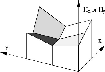
The technique represents the electric and magnetic fields as
simple piecewise functions over many ``elements''
(regions) subdividing a slice through the guide and surrounding media
in the xy plane,
therefore by a finite number of degrees of freedom
(see Fig. 8.4.1).
Each element has a dielectric constant associated with it, allowing arbitrary
stepwise refractive index distributions in the xy plane to be modelled.
Maxwell's equations for propagating solutions of the form
![]() are reduced to a generalized sparse
eigenvalue equation with
are reduced to a generalized sparse
eigenvalue equation with ![]() as the eigenvalue and the bound mode field distributions as the eigenvectors.
For introductory reviews of electromagnetic waveguide bound-mode techniques
see Silvester and Ferari [182]
and Davies [56].
as the eigenvalue and the bound mode field distributions as the eigenvectors.
For introductory reviews of electromagnetic waveguide bound-mode techniques
see Silvester and Ferari [182]
and Davies [56].
Specifically, we used the technique of Fernandez and Lu
[139],
with ![]() and
and ![]() as the field degrees of freedom, for simplicity
using first-order (bilinear) functions to represent these fields over
each element in a two-dimensional grid.
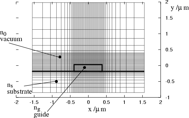
To reach a compromise between flexibility and ease of coding,
the grid of elements was chosen to be
non-uniform
(in order to allow high densities in the regions where fields
changed rapidly,
and low densities in others), but rectangular and separable into a product
of elements in the x and y directions.
See Fig. 8.4.1 which shows an example grid used for calculation.
as the field degrees of freedom, for simplicity
using first-order (bilinear) functions to represent these fields over
each element in a two-dimensional grid.
To reach a compromise between flexibility and ease of coding,
the grid of elements was chosen to be
non-uniform
(in order to allow high densities in the regions where fields
changed rapidly,
and low densities in others), but rectangular and separable into a product
of elements in the x and y directions.
See Fig. 8.4.1 which shows an example grid used for calculation.
This required a generalization of the Fernandez and Lu implementation, and careful consideration of their line-integral terms (which are non-standard for a finite element formulation). Of the many available finite element approaches to dielectric waveguide mode solution, this frequency-domain method was chosen for its absence of `spurious modes' (unphysical numerical solutions), its ability to handle index step discontinuities, its small number of required degrees of freedom, and its matrix sparsity. It does not perform as well as some more complicated methods which represent more field degrees of freedom (for a comparison of some current methods, see [178]).
Rather than emulating a radiative boundary condition
(a notoriously hard task usually requiring an additional
outer iterative
loop, due to the ![]() dependence of the boundary condition),
we enclosed the problem in a large, perfectly-conducting box
of sufficient
size
that the bound mode evanescent fields were negligible on its walls,
rendering the
exact
nature of the boundary condition irrelevant.
However,
the average level spacing of the unbound modes (the `continuum')
decreases with increasing box size,
and especially near cut-off we found that this increases the number
of iterations required to solve the eigenvalue problem
to a given accuracy.
Thus we have a trade-off, and
found that a box size of
dependence of the boundary condition),
we enclosed the problem in a large, perfectly-conducting box
of sufficient
size
that the bound mode evanescent fields were negligible on its walls,
rendering the
exact
nature of the boundary condition irrelevant.
However,
the average level spacing of the unbound modes (the `continuum')
decreases with increasing box size,
and especially near cut-off we found that this increases the number
of iterations required to solve the eigenvalue problem
to a given accuracy.
Thus we have a trade-off, and
found that a box size of ![]() to
to ![]() gave the best compromise
between accuracy and speed.
gave the best compromise
between accuracy and speed.
 |
We used the well-known ARPACK nonsymmeteric sparse eigenvalue solver [133] (essentially a block Lanczos [81,125] iterative solver) to find the 11 lowest eigenmodes of the sparse matrix. Of these, only the lowest 4 were needed to identify the single-mode region in Fig. 8.2, and only the lowest 2 eigenvectors were needed for their electric field information. Our non-uniform elements allowed us to have a high element density across the waveguide and in the adjacent trapping region, but a low density over the much larger box area, keeping the total number of degrees of freedom manageable.