


Next: Sources of error in
Up: Higher-order correction and normalization
Previous: Correction of the eigenwavenumbers
`Automatic' normalisation of states
A feature of the scaling method, as VS realised, is that the eigenstates
found are already normalized in a known fashion.
(This contrasts the BIM, Heller's PWDM for which explicit normalization
is required).
The numerical diagonalization of (6.25) usually returns
eigenvectors normalized so
 ,
corresponding to scaling eigenfunctions with unit tension.
However, we already know the tension of such functions when they are normalized
to unity in the domain
,
corresponding to scaling eigenfunctions with unit tension.
However, we already know the tension of such functions when they are normalized
to unity in the domain  : this is given by (6.27).
Therefore by taking the square root we obtain the
amplitude correction factor,
: this is given by (6.27).
Therefore by taking the square root we obtain the
amplitude correction factor,
 |
(6.29) |
Of course, with (H.9) and the method of Appendix G
we are armed with a rapid tool for checking the normalization of states.
This is done in Fig. 6.8, showing that for high  , the
normalization is correct to 1% for the
, the
normalization is correct to 1% for the  useful states, and
correct to 0.01% for the
useful states, and
correct to 0.01% for the  highest accuracy ones.
The growth of norm errors is random from state to state, and follows a
second power law.
In practice, since the boundary derivatives of the eigenstates are needed
anyway, a final normalization using (H.9) was performed.
If the norm deviates much from 1, it is a very useful indicator that something
is wrong (e.g. a spurious state has been found).
This is probably the single most important use of automatic normalisation.
Such errors are now analysed in the next section.
highest accuracy ones.
The growth of norm errors is random from state to state, and follows a
second power law.
In practice, since the boundary derivatives of the eigenstates are needed
anyway, a final normalization using (H.9) was performed.
If the norm deviates much from 1, it is a very useful indicator that something
is wrong (e.g. a spurious state has been found).
This is probably the single most important use of automatic normalisation.
Such errors are now analysed in the next section.
Figure 6.9:
Growth of tension (2-norm of error from obeying the boundary conditions)
with  of eigenstates returned from a single scaling diagonalization at
 .
The basic method using (6.26) (crosses) and corrected wavenumbers
(6.28) (dots) are shown.
Both show a sixth power law (straight line),
with small deviations from state to state.
Truncation at
.
The basic method using (6.26) (crosses) and corrected wavenumbers
(6.28) (dots) are shown.
Both show a sixth power law (straight line),
with small deviations from state to state.
Truncation at  is due to limitations of the basis set.
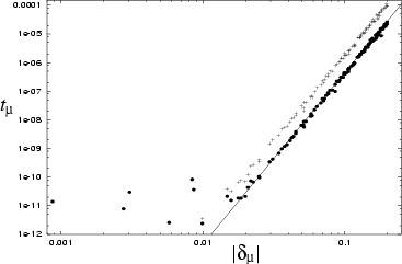 |
Figure 6.10:
Exploration of the effect of weakening the quasi-diagonality of
 .
The dots show the same as Fig. 6.9.
The other sets of points show the tension errors for
.
The dots show the same as Fig. 6.9.
The other sets of points show the tension errors for
 , with the
different choices of
, with the
different choices of  labelled in the upper left corner.
This corresponds to
labelled in the upper left corner.
This corresponds to
 being the dilation deformation with some
`constant' (CO) deformation mixed in (see Table 3.1).
As increases a new type of error emerges
with a different power-law and much greater random state-to-state fluctuations.
Examining the
being the dilation deformation with some
`constant' (CO) deformation mixed in (see Table 3.1).
As increases a new type of error emerges
with a different power-law and much greater random state-to-state fluctuations.
Examining the  boundary errors shows that they are dominated by the
effect of the one or two states with smallest
boundary errors shows that they are dominated by the
effect of the one or two states with smallest  .
.
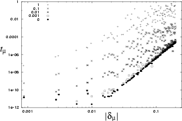 |
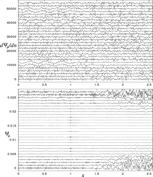
Figure 6.11:
Normal gradients
 (upper) and values
  (lower)
as a function of the boundary coordinate
(lower)
as a function of the boundary coordinate  .
The plots have been displaced vertically by state (with increasing ).
The states correspond to those shown in Fig. 6.5,
except that a better RPW and EPW basis set has been used to reduce
basis-related errors.
The billiard is the 2D quarter stadium at
.
The plots have been displaced vertically by state (with increasing ).
The states correspond to those shown in Fig. 6.5,
except that a better RPW and EPW basis set has been used to reduce
basis-related errors.
The billiard is the 2D quarter stadium at  .
The coordinate is measured from the upper-left to the lower-right
`corner' of the quarter stadium, on the outer edge (which is also present in the
full stadium). The small `blip' at
.
The coordinate is measured from the upper-left to the lower-right
`corner' of the quarter stadium, on the outer edge (which is also present in the
full stadium). The small `blip' at  corresponds to the `kink' in the
stadium boundary.
corresponds to the `kink' in the
stadium boundary.
 |
Next: Sources of error in
Up: Higher-order correction and normalization
Previous: Correction of the eigenwavenumbers
Alex Barnett
2001-10-03